◆Altitude not exceeding 3000 meters;
◆Ambient temperature: -25°C~+40°C;
◆Relative humidity: daily average value not exceeding 95%, monthly average value not exceeding 90%
Vibration acceleration not exceeding 15 m/s2;
◆The surrounding medium has no explosion hazard, no conductive dust, no gas that damages insulation and no metal corrosion.
| Parameter name | Datas | ||
| Rated voltage (V) | DC: 48/110/220;
AC: 220 |
||
| Rated current (A) | 12.5 | ||
| Rated breaking current (A) | DC | 220V, t=20ms | 4 |
| 110V, t=20ms | 8 | ||
| AC | (Phase voltage)220V, cosσ=0.4 | 15 | |
| Life (times) | 20000 | ||
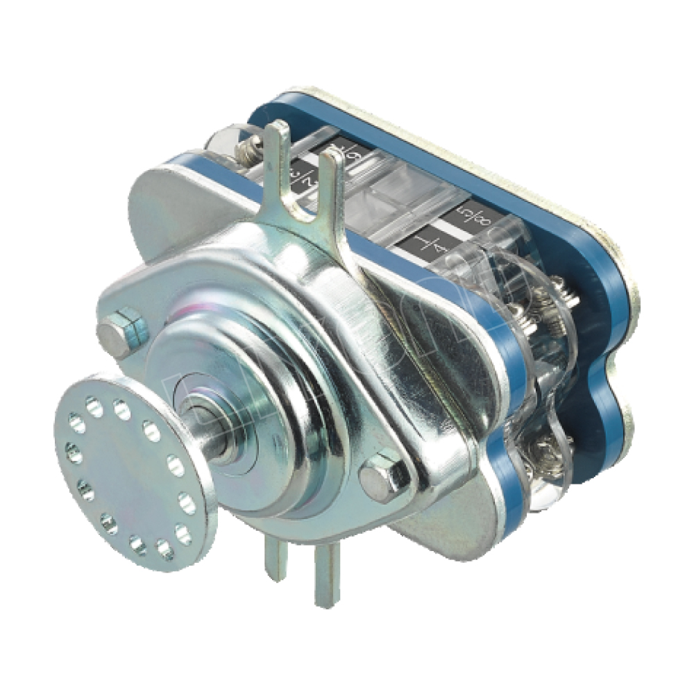
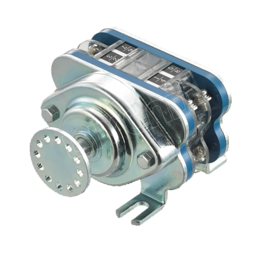
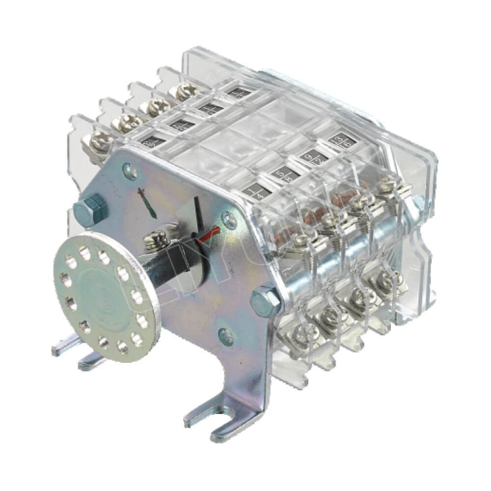
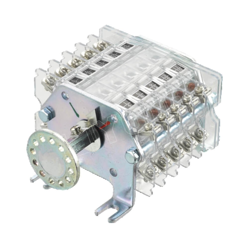
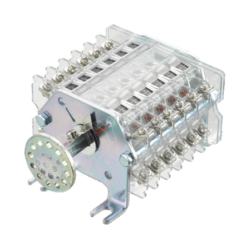
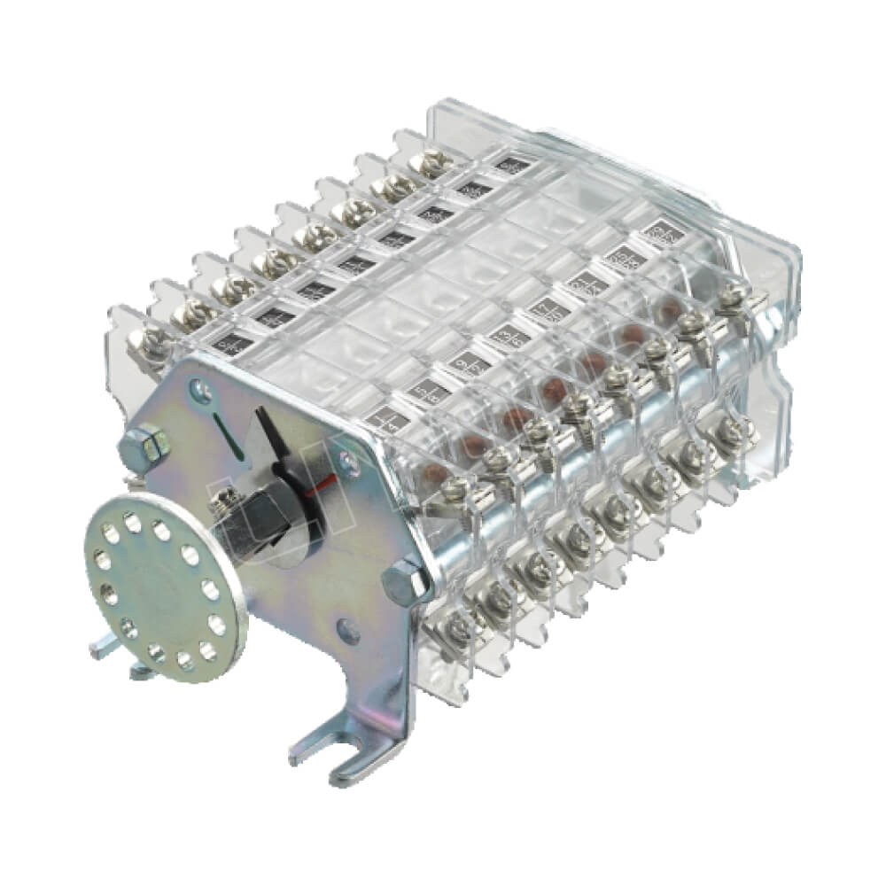
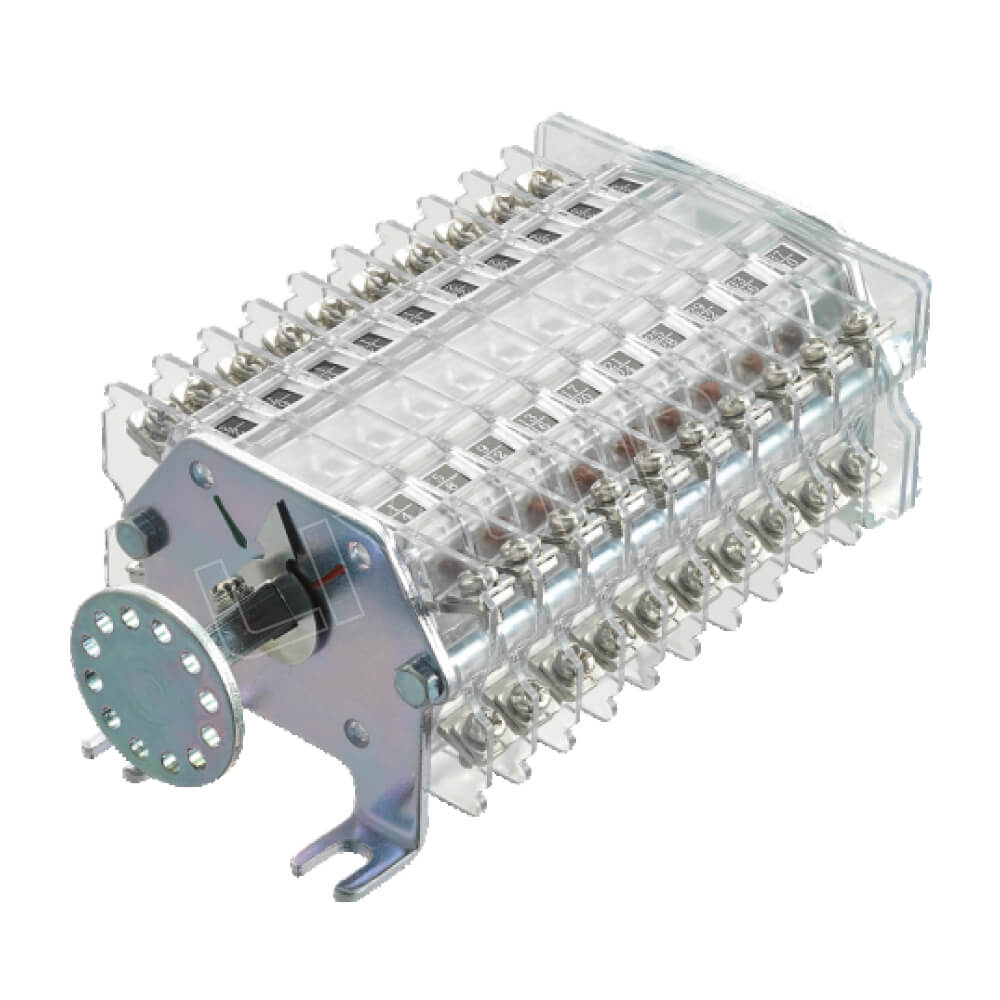
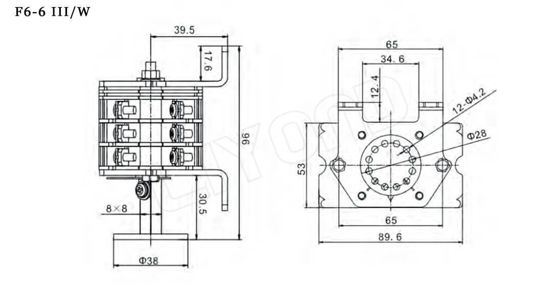
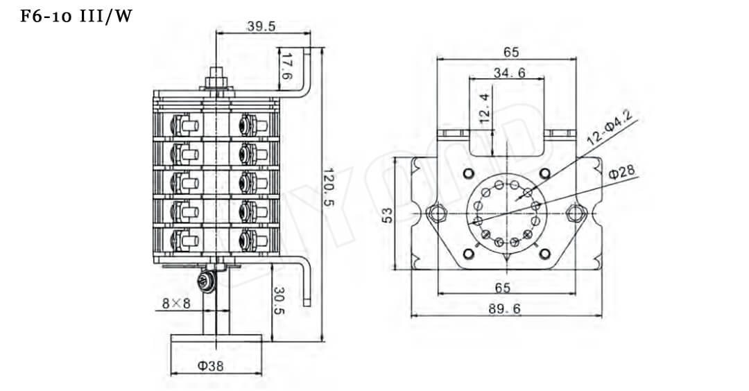
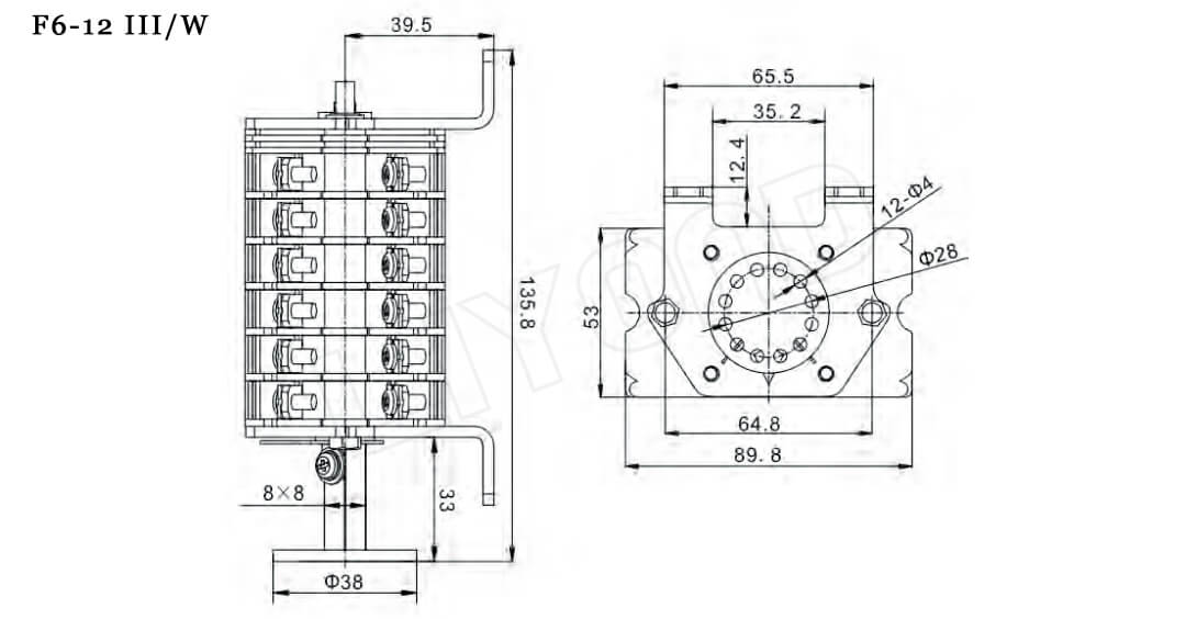
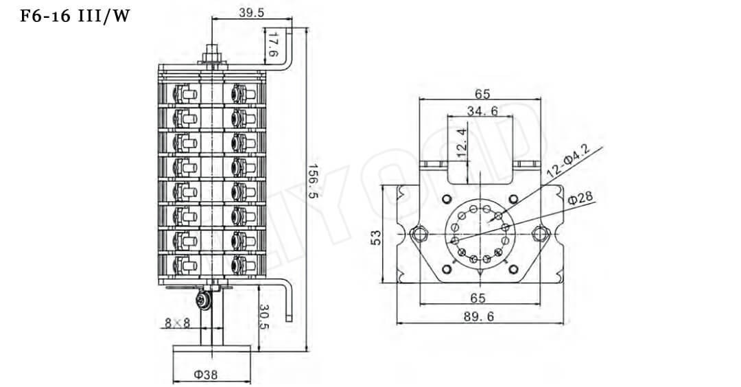
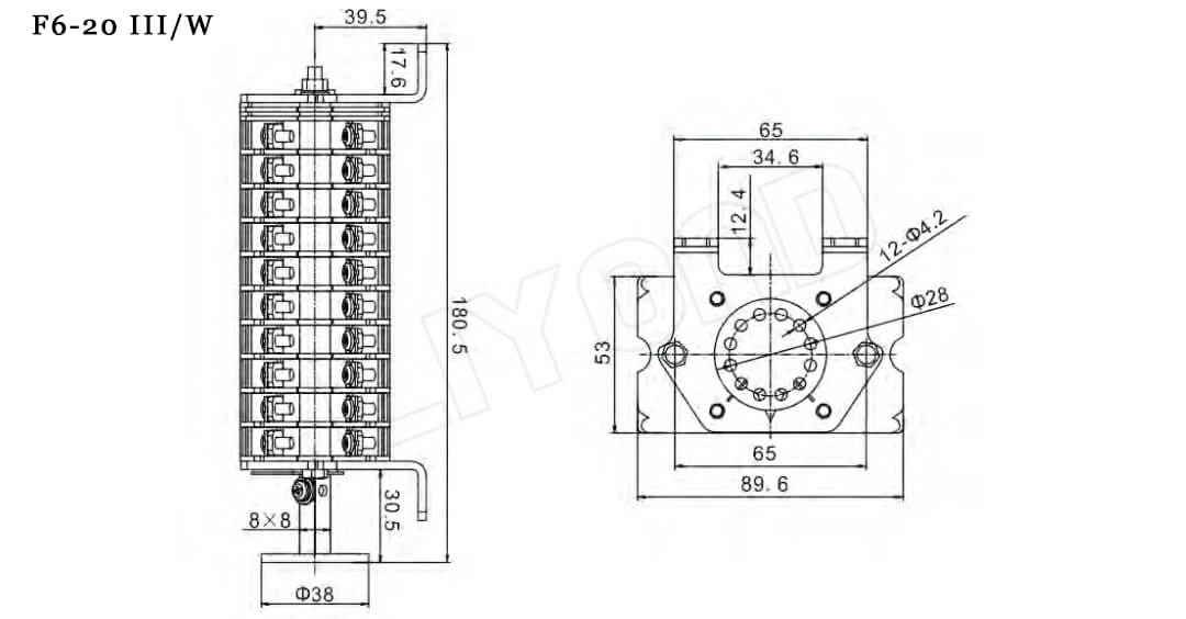
Mechanism and features of F6 Series Auxiliary Switch
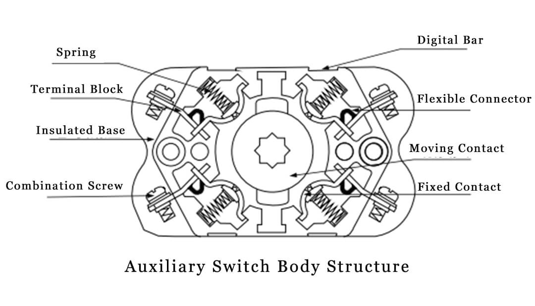
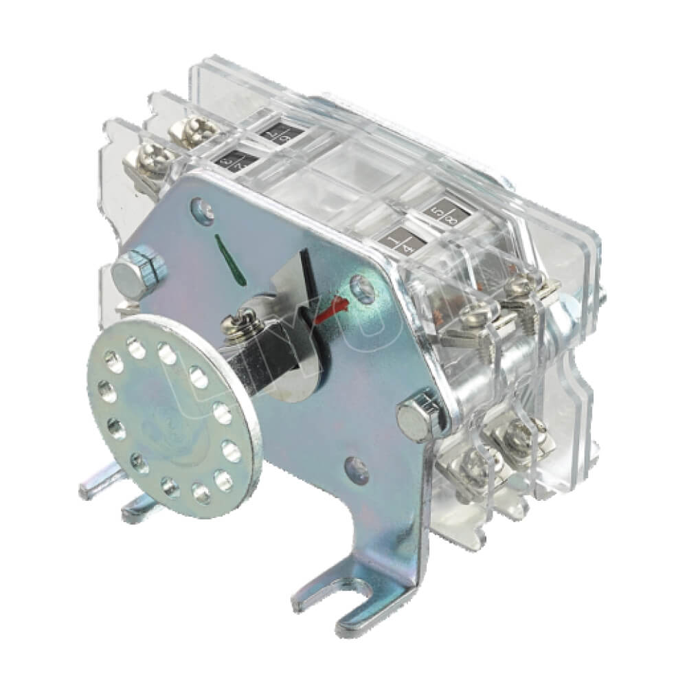
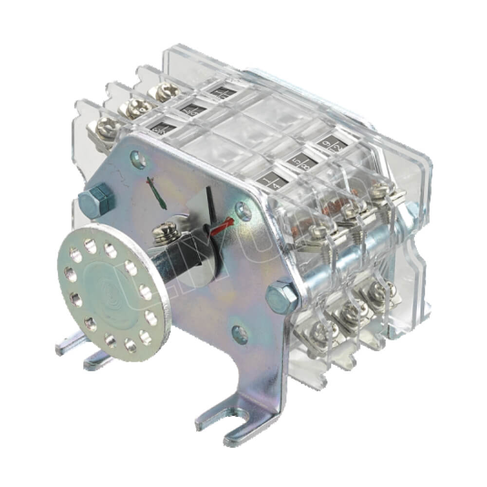
The F6 series auxiliary switch is composed of multiple sections, and the internal structure of the body is shown in the figure. There are numbers on both sides above each section to indicate the number of the contact. The diagonal lines in the same section form a pair of normally open (or normally closed) circuits. The determination of normally open (or normally closed) is displayed by the indicator sheet on the operating shaft. The indicator sheet points to a group of contact limits, indicating that this group is a pair of normally closed contacts (circuits) with reliable contact, and the rest are a pair of normally open contacts.
The contact of the moving and static contacts of this series of auxiliary switches uses a circular sliding crimping method. The pressure between the contacts is generated by a separately set compression spring. The compression spring is non-conductive and far away from the heating part. The hinge joint of the static contact is connected by bare copper wire welding, making the flow performance more reliable.
The time-delay quick-action mechanism is flexible in operation, accurate in delay, and quick in switching. The quick mechanism starts to drive the moving contact to rotate quickly until the end point after the active arm rotates to 65°-75°, and can reliably stay at the end point. Therefore, it has the requirements of delay and quick action.
1 Product name, model, quantity
2 Indicate the number of contact pairs and switch sections, type and installation method
3 Whether to use connection accessories
4 If the user has other special requirements, please specify