.jpg)
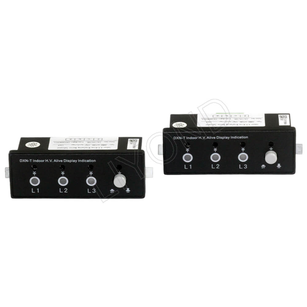
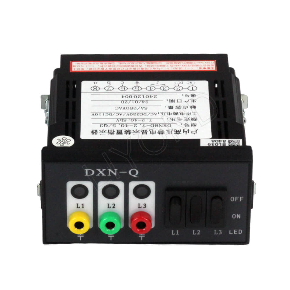
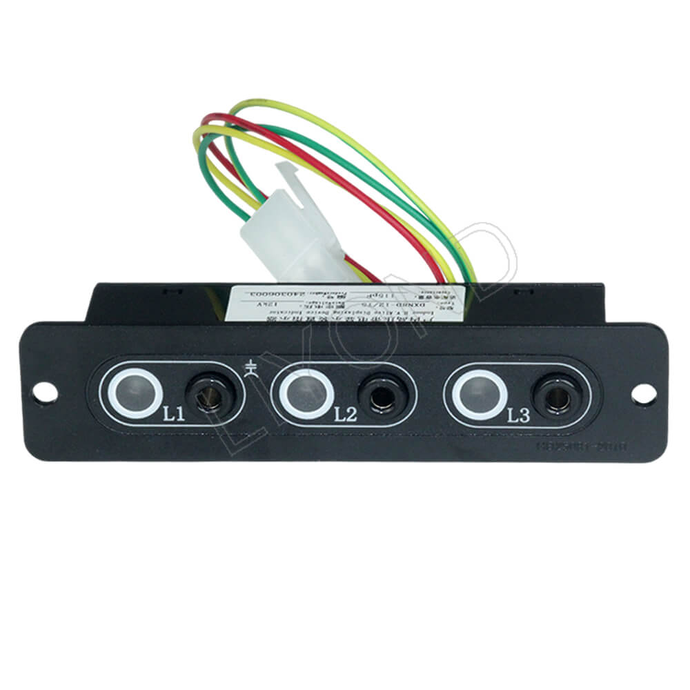
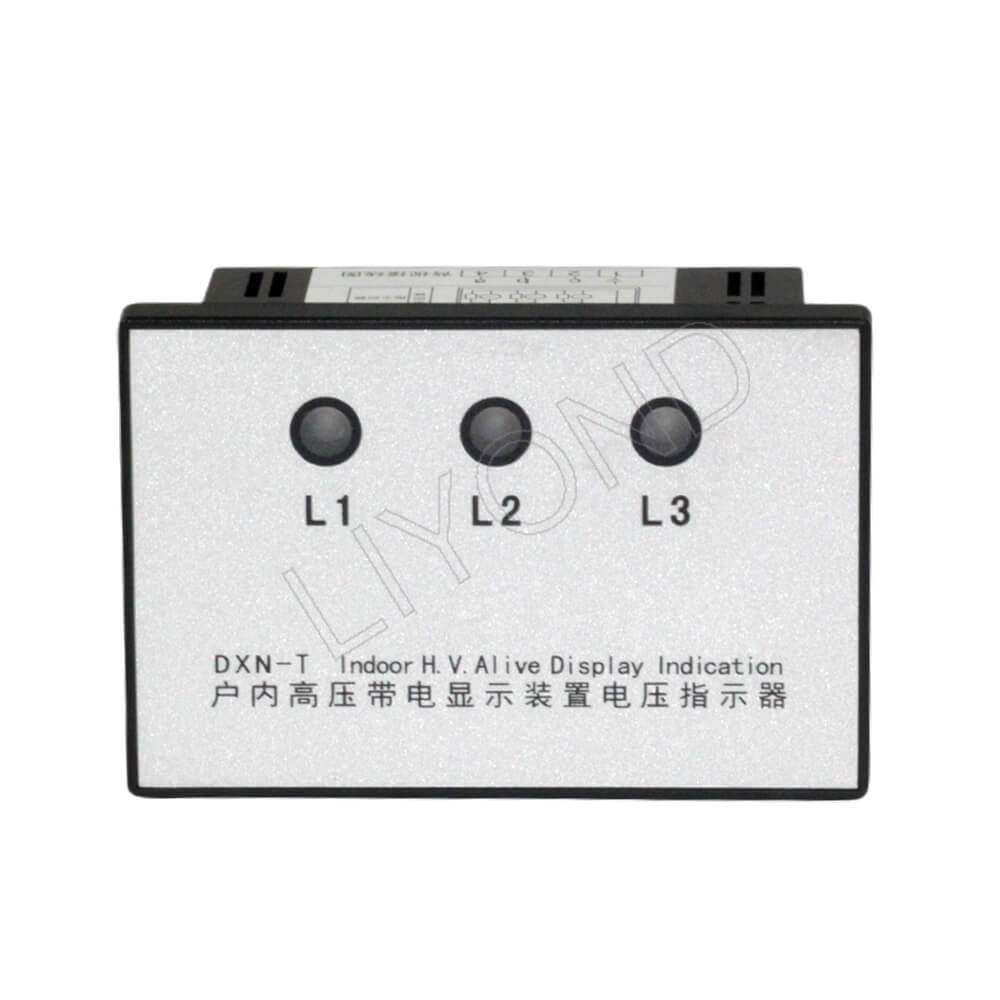
DXN8D-T(Q) series indoor high-voltage live display device is suitable for indoor rated voltage: 6, 12, 20, 27.5, 35kV, frequency of 50Hz switchgear, to reflect the display device set at the high-voltage circuit live condition.
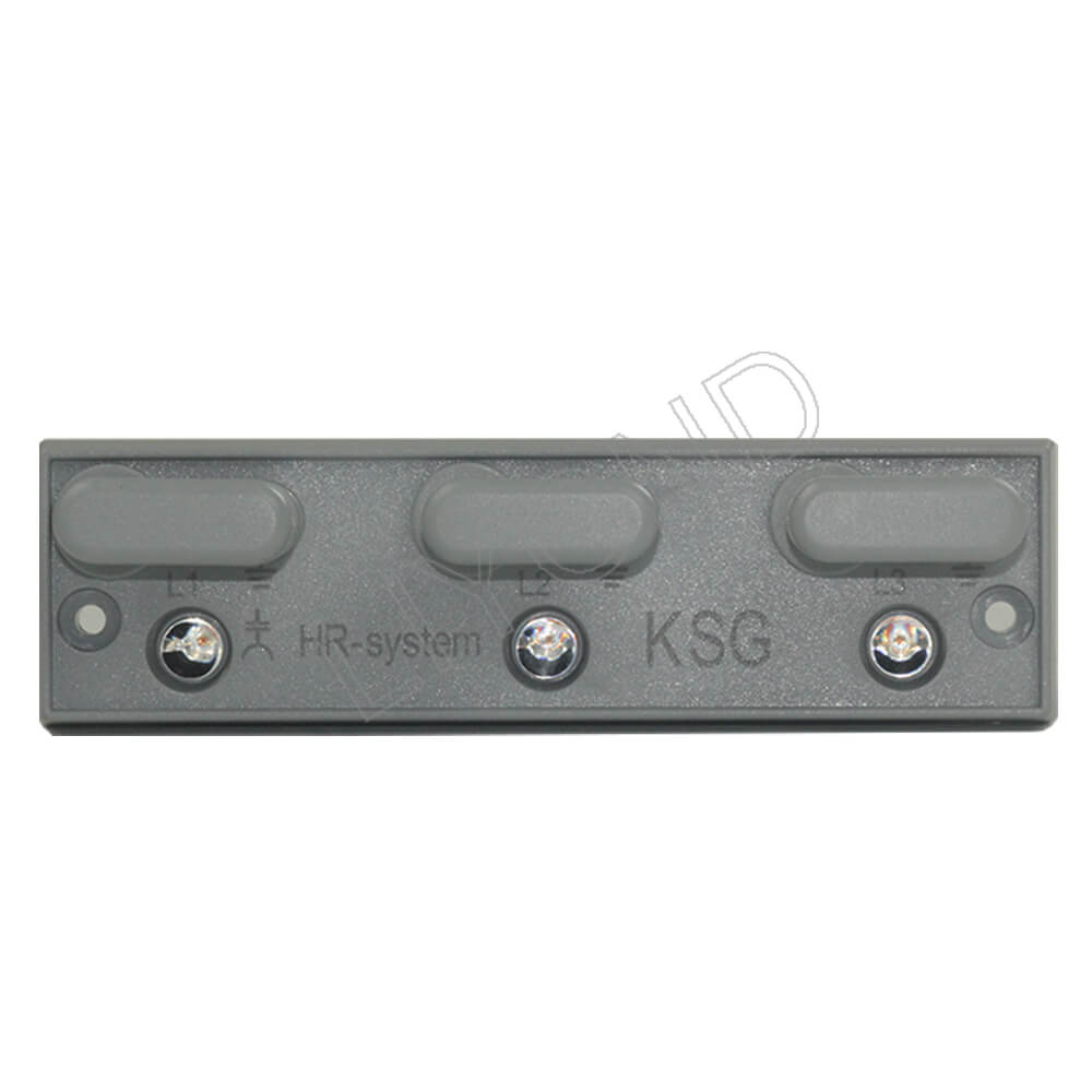
The pillar insulator sensor in the display device can be matched with various types of high-voltage switchgear, disconnecting switches and earthing switches.
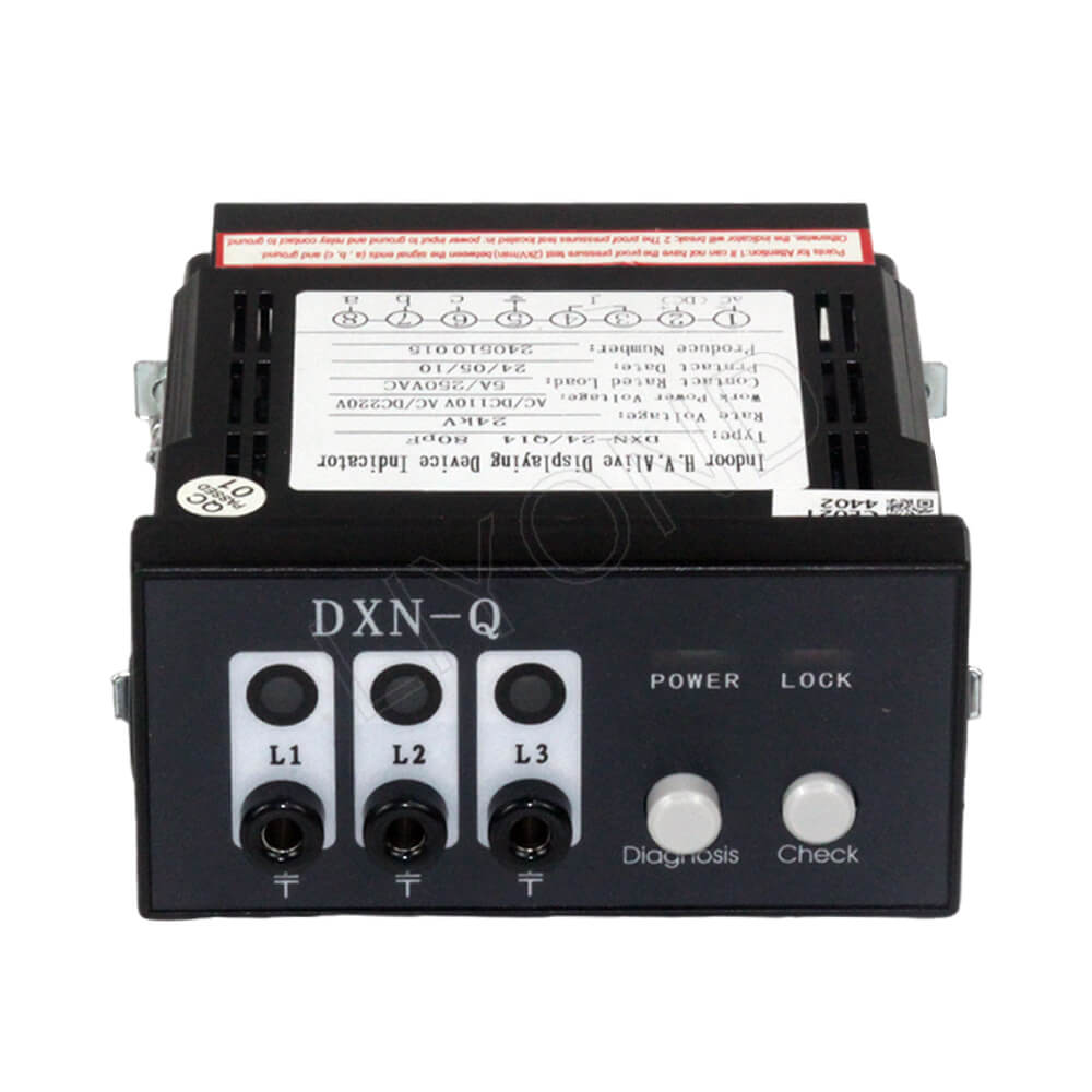
The display device can not only prompt the circuit charged condition, but also with electromagnetic locks, to achieve the mandatory locking switchgear operating handle and net door. It can achieve the purpose of preventing the electrically charged switch from being closed or grounded, preventing accidental entry into electrically charged intervals, and improving the error-proof performance of the switchgear.
Executive standard
GB25081-2010 HV live display device(VPIS)
DL/T533-93 condensation and pollution test condition for indoor AC HV switchgear and components
IEC61958:2000 HV prefabricated switchgear assembly and control assembly-live displaying device
Applying environment conditions
1.Environment temperature: upper limit value not more than +40℃,lower limit value not lower than -25℃, special area not lower than -35℃.
2.Sea level: no more than 1000m.
3.Atmospheric conditions: RH daily average value not more than 95%, month average value not more than 90%, steam pressure daily average value not more than 2.2kPa, month average value not more than 1.8kPa.
4.Environment condition: no obvious filth, no flammable, no explosive chemical etcing and salt fog place.
.jpg)
Voltage indicator adaptation capacity parameter table
| Rated line voltage level (kV) | Rated phase voltage | Adaptive sensor capacity (pF) |
|||
| Working voltage (V) | Working current (μA) | Phase-to-phase voltage when the phases between the test points match (V) | Phase-to-phase voltage when the phases between the test points are inconsistent (V) | ||
| 3.6 | 80-100 | 117 | <AC30 | >AC80 | 180(±15) |
| 7.2 | 80-100 | 196 | 150(±15) | ||
| 12 | 80-100 | 250 | 115(±15) | ||
| 24 | 80-100 | 348 | 80(±10) | ||
| 40.5 | 80-100 | 330 | 45(±10) | ||
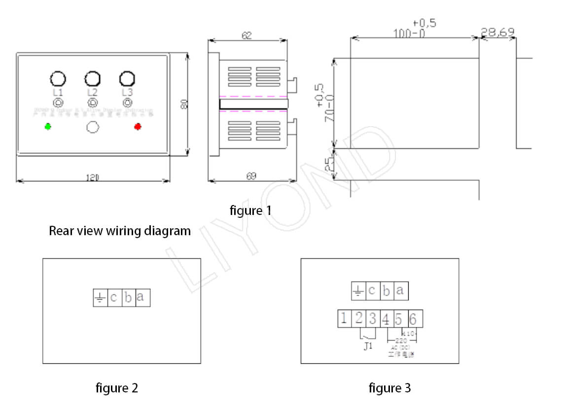
Appearance and mounting hole processing dimensions